4-4
For further information on IC synchro replacement, alignment, and theory, refer to Military
Handbook, Synchros, Description and Operation, (MIL-HDBK-225A).
Q-1. What two characteristics of IC synchros cause them to differ from standard synchros?
STEP-TRANSMISSION SYSTEMS
All of the synchro units we have discussed operate on alternating current. In applications where
alternating current is not available, there is a need for a system that can use direct current. The STEP-
TRANSMISSION SYSTEM (sometimes referred to as the step-by-step system) is such a system.
A geared step-transmission system is often used to drive compass repeaters on naval vessels and
merchant ships having dc power.
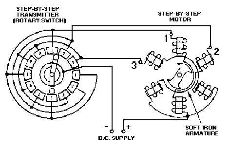
Although many variations are used, the simplified step-by-step transmission system shown in figure
4-3 is typical. In this system, a step transmitter and a step motor are used together to transmit angular data
(information) between remote locations. When rotated, the shaft of the step transmitter periodically
switches a dc excitation voltage from one pair of coils to another in the step motor. The step motor, which
is the receiver in the system, responds to this varying excitation by rotating an amount that is proportional
to the transmitter’s shaft position.
Figure 4-3.—Step-by-step transmission system.
The stator of this step motor has six field coils spaced 60 degrees apart. The coils are connected in
three groups of two coils each, with opposite coils connected in series. One end of each pair of coils is
connected to one of the brushes in the step transmitter. The other ends of the coils are connected to the
other side of the dc supply voltage through a common lead. As the rotor of the step transmitter is turned,
the corresponding coils in the step motor are energized in sequence, producing a rotating step-by-step
stator field. Thus, the motor rotates in abrupt increments or steps rather than smoothly.


