4-8
compensate for voltage inaccuracies and phase shifts, may be mounted either inside or outside the
resolver housing.
A cylindrical frame with a standardized mounting flange houses the assembled resolver. External
and internal connections can be made to an insulated terminal board on the rear of the housing. Miniature
resolvers often have lead wires brought out through the rear of the resolver, eliminating the need for a
terminal block. A reference line is scribed on the face of the housing for alignment with a similar line on
the end of the rotor shaft. These are used in determining coarse electrical zero.
Basically, a resolver is a transformer in which the secondary windings can be rotated with respect to
the primary windings. Consequently, the amount of magnetic coupling between the primary and the
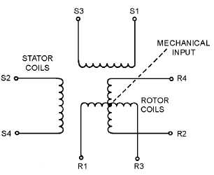
secondary is variable. In the most common form, a resolver consists of a stator and a rotor, each having
two separate windings placed precisely at right angles to each other as shown in figure 4-6.
Figure 4-6.—Resolver schematic.
Since the two stator windings are physically and electrically at right angles to each other, there is no
magnetic coupling between them. The stator windings are mounted on the resolver housing and are
stationary with respect to it.
Similarly, the rotor windings of the resolver are wound at right angles to each other. Hence, there is
no magnetic coupling between the two windings. The rotor windings are mounted on the rotor shaft and
turn with it. The rotor is capable of unlimited rotation. Thus, the rotor windings can be set at any angle
with respect to the stator windings.
Because of the 90º physical and electrical relationships, the resolver has the ability to separate a
quantity into its two right-angle components. This is called RESOLUTION.
Figure 4-7 illustrates the use of a resolver in solving a resolution problem. Assume that a voltage, E,
and an angle, R, represent the magnitude and direction of a known quantity. To determine the two right-
angle components of the quantity, feed the magnitude of the quantity to one stator coil and physically turn
the rotor through angle R. The input voltage (E) induces voltage E1 and E2 in the two rotor coils. The
values of these rotor voltages represent the vertical and horizontal components of the known quantity and
depend on both the value of E and the angle (R) through which the rotor was turned.


