4-5
NOTE: The theory of the step-by-step motor is similar to that involved in positioning the bar magnet
(chapter 1, fig. 1-10).
For ease of explanation, we will replace the step transmitter with a battery as we discuss the
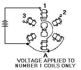
operation of the step motor. If, as shown in view A of figure 4-4, we apply the dc battery voltage across
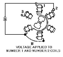
the number 1 coils only, the armature will turn to the position shown. When we apply the voltage also to
the number 2 coils, the armature turns to a position midway between the number 1 and number 2 coils,
view B. If we now disconnect the number 1 coils, the armature turns until it lines up with the number 2
coils, view C. View D shows the number 2 and 3 coils connected and the armature rotated one step
further. As long as this process is continued, the armature can be rotated through 360 degrees.
Figure 4-4A.—Step-by-step motor in various positions. VOLTAGE APPLIED TO NUMBER 1 COILS ONLY.
Figure 4-4B.—Step-by-step motor in various positions. VOLTAGE APPLIED TO NUMBER 1 AND NUMBER 2
COILS.


