4-6
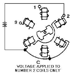
Figure 4-4C.—Step-by-step motor in various positions. VOLTAGE APPLIED TO NUMBER 2 COILS ONLY.
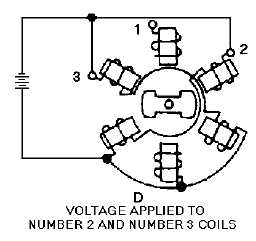
Figure 4-4D.—Step-by-step motor in various positions. VOLTAGE APPLIED TO NUMBER 2 AND NUMBER 3
COILS.
In actual operation, the step-by-step motor is driven by a step transmitter (rotary switch) as shown in
figure 4-3. As the switch is rotated, it applies voltage first to coil 1, and then in sequence to 1 and 2
together, coil 2 only, coils 2 and 3 together, coil 3 only, and so on, until the complete revolution is made.
As a result, the armature turns in 30-degree steps that follow the rotation of the rotary switch. The rotating
arm of the switch can be turned mechanically to angles between zero and 360º in 30-degree steps. The
actual angle through which the arm is rotated depends on the specific data to be transmitted by the
system. Real systems may transmit data in greater or lesser steps than 30 degrees, depending on system
design.
An important point in this type of system is that because the armature is soft iron, either end of the
armature may turn and line up with the energized coils. For this reason, a hand reset control is provided
on the step-by-step motor. This permits an operator to align the receiver with the transmitter each time the
power supply is energized.


