4-2
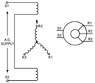
Figure 4-1.—IC synchro schematic diagrams.
IC synchros operate on the same principles of interacting magnetic fields as other synchros, but
differ in direction of shaft rotation and amount of torque obtainable. When an IC transmitter and IC
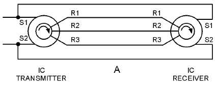
receiver are connected in parallel as shown in view A of figure 4-2, the shaft of the IC receiver follows
the rotation of the IC transmitter shaft. In view B, the IC transmitter is replaced by a synchro transmitter;
the IC receiver shaft now turns in a direction opposite to that of the synchro transmitter. Voltages that
cause counterclockwise rotation of a standard synchro shaft cause clockwise rotation of an IC synchro
shaft. When it is desirable to have the IC synchro receiver turn in an opposite direction from that of the
transmitter, the connections are as shown in view C. For a standard synchro receiver to follow the rotation
of an IC transmitter, their connections must be made as shown in view D.
Figure 4-2A.—IC versus standard synchro connections.


