3-21
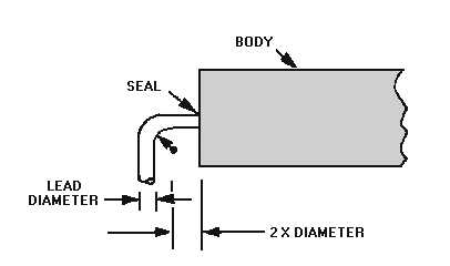
Figure 3-13.—Minimum distance lead bend to component body.
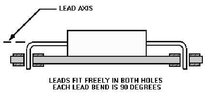
Leads must be approximately 90 degrees from their major axis to ensure free movement in hole
terminations, as shown in figure 3-14.
Figure 3-14.—Ideal lead formation.
In lead-forming, the lead must not be damaged by nicking.
Energy from the bending action must not be transmitted into the component body.
COMPONENT PLACEMENT.—Where possible, parts are remounted or reassembled as they
were in the original manufacturing process. To aid recognition, manufacturers use a coding system of
colored dots, bands, letters, numbers, and signs. Replacement components are mounted to make all
identification markings readable without disturbing the component. When components are mounted like
the original, all the identification markings are readable from a single point.
Component identification reads uniformly from left to right, top to bottom, unless polarity
requirements determine otherwise, as shown in figure 3-15. To locate the top, position the board so the
part number may be read like a page in a book. By definition, the top of the board is the edge above the
part number.


