2-47
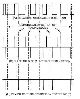
Ppm can be generated in several ways, but we will discuss one of the simplest. Figure 2-46 shows
three waveforms associated with developing ppm from pdm. The pdm pulse train is applied to a
differentiating circuit. (Differentiation was presented in NEETS, Module 9, Introduction to
Wave-Generation and Wave-Shaping Circuits.) This provides positive- and negative-polarity pulses that
correspond to the leading and trailing edges of the pdm pulses. Considering pdm and its generation, you
can see that each pulse has a leading and trailing edge. In this case the position of the leading edge is
fixed, whereas the trailing edge is not, as shown in view (A) of figure 2-46. The resultant pulses after the
differentiation are shown in view (B). The negative pulses are position-modulated in accordance with the
modulating waveform. Both the negative and positive pulse are then applied to a rectification circuit. This
application eliminates the positive, non-modulated pulses and develops a ppm pulse train, as shown in
view (C).
Figure 2-46.—Pulse-position modulation (ppm).
PULSE-FREQUENCY MODULATION.—Pfm is a method of pulse modulation in which the
modulating wave is used to frequency modulate a pulse-generating circuit. For example, the pulse rate
may be 8,000 pulses per second (pps) when the signal voltage is 0. The pulse rate may step up to 9,000
pps for maximum positive signal voltage, and down to 7,000 pps for maximum negative signal voltage.
Figure 2-47, views (A), (B), and (C) show three typical waveforms for pfm. This method of modulation is
not used extensively because of complicated pfm generation methods. It requires a stable oscillator that is
frequency modulated to drive a pulse generator. Since the other forms of ptm are easier to achieve, they
are commonly used.
Figure 2-47A.—Pulse-frequency modulation (pfm). MODULATION.


