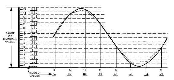
2-51
a usable reconstructed modulation curve. At the sampling rate of figure 2-50 and with a 4-element binary
code, 128 bits (presence or absence of pulses) must be transmitted for each cycle of the modulating
frequency. At the sampling rate of figure 2-51, only 32 bits are required; at the minimum sampling rate,
only 8 bits are required.
Figure 2-51.—Pulse-code modulation of a quantized wave (32 bits).
As a matter of convenience, especially to simplify the demodulation of pcm, the pulse trains actually
transmitted are reversed from those shown in figures 2-49, 2-50, and 2-51; that is, the pulse with the
lowest binary value (least significant digit) is transmitted first and the succeeding pulses have increasing
binary values up to the code limit (most significant digit). Pulse coding can be performed in a number of
ways using conventional circuitry or by means of special cathode ray coding tubes. One form of coding
circuit is shown in figure 2-52. In this case, the pulse samples are applied to a holding circuit (a capacitor
which stores pulse amplitude information) and the modulator converts pam to pdm. The pdm pulses are
then used to gate the output of a precision pulse generator that controls the number of pulses applied to a
binary counter. The duration of the gate pulse is not necessarily an integral number of the repetition
pulses from the precisely timed clock-pulse generator. Therefore, the clock pulses gated into the binary
counter by the pdm pulse may be a number of pulses plus the leading edge of an additional pulse. This
"partial" pulse may have sufficient duration to trigger the counter, or it may not. The counter thus
responds only to integral numbers, effectively quantizing the signal while, at the same time, encoding it.
Each bistable stage of the counter stores ZERO or a ONE for each binary digit it represents (binary 1110
or decimal 14 is shown in figure 2-52). An electronic commutator samples the 20, 21, 22, and 23 digit
positions in sequence and transmits a mark or space bit (pulse or no pulse) in accordance with the state of
each counter stage. The holding circuit is always discharged and reset to zero before initiation of the
sequence for the next pulse sample.


