2-22
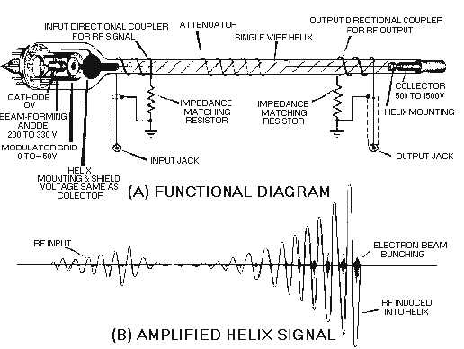
Figure 2-15.—Functional diagram of a twt.
In a typical twt, the electron beam is directed down the center of the helix while, at the same time, an
rf signal is coupled onto the helix. The electrons of the beam are velocity-modulated by the electric fields
produced by the rf signal.
Amplification begins as the electron bunches form and release energy to the signal on the helix. The
slightly amplified signal causes a denser electron bunch which, in turn, amplifies the signal even more.
The amplification process is continuous as the rf wave and the electron beam travel down the length of
the tube.
Any portion of the twt output signal that reflects back to the input will cause oscillations within the
tube which results in a decrease in amplification. Attenuators are placed along the length of the helix to
prevent reflections from reaching the input. The attenuator causes a loss in amplitude, as can be seen in
figure 2-15, view (B), but it can be placed so as to minimize losses while still isolating the input from the
output.
The relatively low efficiency of the twt partially offsets the advantages of high gain and wide
bandwidth. The internal attenuator reduces the gain of the tube, and the power required to energize the
focusing magnet is an operational loss that cannot be recovered. The twt also produces heat which must
be dissipated by either air-conditioning or liquid-cooling systems. All of these factors reduce the overall
efficiency of the twt, but the advantages of high gain and wide bandwidth are usually enough to overcome
the disadvantages.
The Backward-Wave Oscillator
The BACKWARD-WAVE OSCILLATOR (bwo) is a microwave-frequency, velocity-modulated
tube that operates on the same principle as the twt. However, a traveling wave that moves from the


