2-17
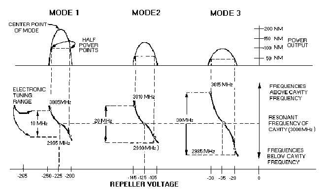
Figure 2-12 illustrates the ELECTRONIC TUNING (tuning by altering the repeller voltage) range
and output power of a reflex klystron. Each mode has a center frequency of 3,000 megahertz which is
predetermined by the physical size of the cavity. The output power increases as the repeller voltage is
made more negative. This is because the transit time of the electron bunches is decreased.
Figure 2-12.—Electronic tuning and output power of a reflex klystron.
Electronic tuning does not change the center frequency of the cavity, but does vary the frequency
within the mode of operation. The amount the frequency can be varied above or below the center
frequency is limited by the half-power points of the mode, as shown in figure 2-12. The center frequency
can be changed by one of two methods One method, GRID-GAP TUNING, varies the cavity frequency
by altering the distance between the grids to change the physical size of the cavity. This method varies the
capacitance of the cavity by using a tuning screw to change the distance between the grids mechanically.
The cavity can also be tuned by PADDLES or SLUGS that change the inductance of the cavity.
Q-20. What element of the reflex klystron replaces the output cavity of a normal klystron?
Q-21. When the repealer potential is constant, what property of the electron determines how long it will
remain in the drift space of the reflex klystron?
Q-22. The constant-speed electrons of an electron bunch in a reflex klystron must remain in the repeller
field for what minimum time?
Q-23. If the constant-speed electrons in a reflex klystron remain in the repeller field for 1 3/4 cycles,
what is the mode of operation?


