2-20
The Navy student of electronics will encounter the dBm system of measurement most often as a
figure indicating the receiver sensitivity of radar or communications equipment. Typically, a radar
receiver will be rated at approximately
-
107 dBm, which means the receiver will detect a signal 107 dB
below 1 milliwatt.
The importance of understanding the decibel system of measurement can easily be seen in the case
of receiver-sensitivity measurements. At first glance a loss of 3 dBm from a number as large as
-
107
dBm seems insignificant; however, it becomes extremely important when the number indicates receiver
sensitivity in the decibel system. When the sensitivity falls to
-
104 dBm, the receiver will only detect a
signal that is twice as large as a signal at
-
107 dBm.
The Traveling-Wave Tube
The TRAVELING-WAVE TUBE (twt) is a high-gain, low-noise, wide-bandwidth microwave
amplifier. It is capable of gains greater than 40 dB with bandwidths exceeding an octave. (A bandwidth of
1 octave is one in which the upper frequency is twice the lower frequency.) Traveling-wave tubes have
been designed for frequencies as low as 300 megahertz and as high as 50 gigahertz. The twt is primarily a
voltage amplifier. The wide-bandwidth and low-noise characteristics make the twt ideal for use as an rf
amplifier in microwave equipment.
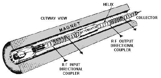
The physical construction of a typical twt is shown in figure 2-13. The twt contains an electron gun
which produces and then accelerates an electron beam along the axis of the tube. The surrounding magnet
provides a magnetic field along the axis of the tube to focus the electrons into a tight beam. The HELIX,
at the center of the tube, is a coiled wire that provides a low-impedance transmission line for the rf energy
within the tube. The rf input and output are coupled onto and removed from the helix by directional
couplers that have no physical connection to the helix. If the rf energy is transported on coaxial cables, the
coaxial couplers are wound in a helical manner similar to that shown in figure 2-13. If the rf energy is
transported in waveguides, waveguide directional couplers are used. The attenuator prevents any reflected
waves from traveling back down the helix.
Figure 2-13.—Physical construction of a twt.
A simplified version of twt operation is shown in figure 2-14. In the figure, an electron beam is
passing along a nonresonant transmission line represented by a straight wire. The input to the
transmission line is an rf wave which travels on the line from input to output. The line will transport a


