2-14
oscillations. The electron beam is turned around by a negatively charged electrode that repels the beam.
This negative element is the repeller mentioned earlier. This type of klystron oscillator is called a reflex
klystron because of the reflex action of the electron beam.
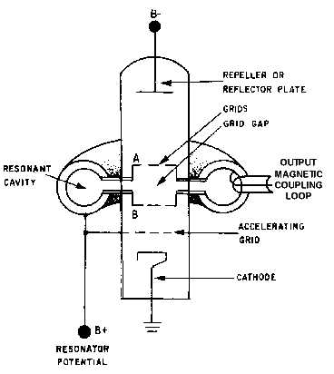
Figure 2-9.—Functional diagram of a reflex klystron.
Three power sources are required for reflex klystron operation: (1) filament power, (2) positive
resonator voltage (often referred to as beam voltage) used to accelerate the electrons through the grid gap
of the resonant cavity, and (3) negative repeller voltage used to turn the electron beam around. The
electrons are focused into a beam by the electrostatic fields set up by the resonator potential (B+) in the
body of the tube. Note in figure 2-9 that the resonator potential is common to the resonator cavity, the
accelerating grid, and the entire body of the tube.
The resonator potential also causes the resonant cavity to begin oscillating at its natural frequency
when the tube is energized. These oscillations cause an electrostatic field across the grid gap of the cavity
that changes direction at the frequency of the cavity. The changing electrostatic field affects the electrons
in the beam as they pass through the grid gap. Some are accelerated and some are decelerated, depending
upon the polarity of the electrostatic field as they pass through the gap. Figure 2-10, view (A), illustrates
the three possible ways an electron can be affected as it passes through the gap (velocity increasing,
decreasing, or remaining constant). Since the resonant cavity is oscillating, the grid potential is an
alternating voltage that causes the electrostatic field between the grids to follow a sine-wave curve as
shown in figure 2-10, view (B). As a result, the velocity of the electrons passing through the gap is
affected uniformly as a function of that sine wave. The amount of velocity change is dependent on the
strength and polarity of the grid voltage.


