2-11
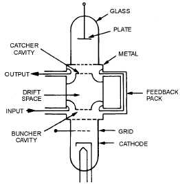
Figure 2-7A.—Functional and schematic diagram of a two-cavity klystron.
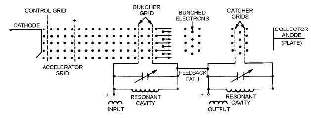
Figure 2-7B.—Functional and schematic diagram of a two-cavity klystron.
The function of the CATCHER GRIDS is to absorb energy from the electron beam. The catcher
grids are placed along the beam at a point where the bunches are fully formed. The location is determined
by the transit time of the bunches at the natural resonant frequency of the cavities (the resonant frequency
of the catcher cavity is the same as the buncher cavity). The location is chosen because maximum energy
transfer to the output (catcher) cavity occurs when the electrostatic field is of the correct polarity to slow
down the electron bunches.
The two-cavity klystron in figure 2-7A and B may be used either as an oscillator or an amplifier. The
configuration shown in the figure is correct for oscillator operation. The feedback path provides energy of
the proper delay and phase relationship to sustain oscillations. A signal applied at the buncher grids will
be amplified if the feedback path is removed.
Q-11. What is the basic principle of operation of a klystron?


