2-27
left side of the electron's path and subtracts from the permanent magnetic field on the right side. This
action weakens the field on the right side; therefore, the electron path bends to the right (clockwise). If the
strength of the magnetic field is increased, the path of the electron will have a sharper bend. Likewise, if
the velocity of the electron increases, the field around it increases and the path will bend more sharply.
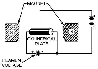
A schematic diagram of a basic magnetron is shown in figure 2-21A. The tube consists of a
cylindrical plate with a cathode placed along the center axis of the plate. The tuned circuit is made up of
cavities in which oscillations take place and are physically located in the plate.
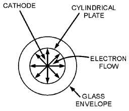
When no magnetic field exists, heating the cathode results in a uniform and direct movement of the
field from the cathode to the plate, as illustrated in figure 2-21B. However, as the magnetic field
surrounding the tube is increased, a single electron is affected, as shown in figure 2-22. In figure 2-22,
view (A), the magnetic field has been increased to a point where the electron proceeds to the plate in a
curve rather than a direct path.
Figure 2-21A.—Basic magnetron. SIDE VIEW.
Figure 2-21B.—Basic magnetron. END VIEW OMITTING MAGNETS.


