4-50
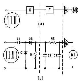
be employed to use this frequency-to-voltage relationship to operate an indicator. The block diagram in
view (A) of figure 4-44 represents one simple circuit which may be used to perform this function. In this
circuit, the basic counter is fed into a low-pass filter and an amplifier with a meter that is calibrated in
units of frequency.
Figure 4-44.—Basic frequency counter.
A typical schematic diagram is shown in view (B). The positive pulses from the counter are filtered
by C2, R2, and C3. The positive dc voltage from the filter is applied to the input of amplifier A. This
voltage increases with frequency; as a consequence, the current through the device increases. Since
emitter or cathode current flows through M1, an increase in amplifier current causes an increase in meter
deflection. The meter may be calibrated in units of time, frequency, revolutions per minute, or any
function based upon the relationship of output voltage to input frequency.
Q25. What establishes the value of the current that flows in the output of figure 4-43?
Q26. What is the purpose of D1 in figure 4-43?
Negative Counters
Reversing the connections of diodes D1 and D2 in the positive-counter circuit (view (A) of figure 4-
43) will cause the circuit to respond to negative pulses and become a negative-counter circuit. Diode D2
conducts during the time the negative pulse is applied and current flows in the opposite direction through
R1, as was indicated by the arrow. At the end of the negative pulse, D1 conducts and discharges C1. The
current through R1 increases with an increase in pulse frequency as before. However, if the voltage
developed across R1 is applied to the same control circuit, as shown in view (A) of figure 4-44, the
increase in current will be in a negative direction and the amplifier will conduct less. Thus, the effect is
opposite to that of the positive counter.
Step-by-Step (Step) Counters
The STEP-BY-STEP (STEP) COUNTER is used as a voltage multiplier when a stepped voltage
must be provided to any device which requires such an input. The step counter provides an output which
increases in one-step increments for each cycle of the input. At some predetermined level, the output
voltage reaches a point which causes a circuit, such as a blocking oscillator, to be triggered.


