4-46
Since you are familiar with the basic current regulating circuitry, let's examine in detail how the
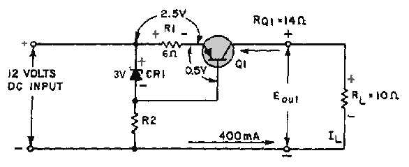
various components work to maintain the constant 400-milliampere output. Refer to the schematic shown
in figure 4-43. Remember a decrease in load resistance causes a corresponding increase in current flow. In
the example shown, the load resistance R
L
has dropped from 15 ohms to 10 ohms. This results in a larger
voltage drop across R1 because of the increased current flow. The voltage drop has increased from 2.4
volts to 2.5 volts. Of course, the voltage drop across CR1 remains constant at 9 volts due to its regulating
ability. Because of the increased voltage drop across R1, the forward bias on Q1 is now 0.5 volt. Since the
forward bias of Q1 has decreased, the resistance of the transistor increases from 9 ohms to 14 ohms.
Notice that the 5 ohm increase in resistance across the transistor corresponds to the 5 ohm decrease in the
load resistance. Thus, the total resistance around the outside loop of the circuit remains constant. Since
the circuit is a current regulator, you know that output voltages will vary as the regulator maintains a
constant current output. In the figure, the voltage output is reduced to 4 volts, which is computed by
multiplying current (I) times resistance (R) (400 mA
10 ohms = 4 volts).
Figure 4-43.—Current regulator (with a decrease in R
L).
Q36.
In figure 4-40, when there is an increase in the load resistance (R L), the resistance of R V
increases/decreases (which one) to compensate for the change.
Q37.
In figure 4-43 any decrease in the base-emitter forward bias across Q1 results in an increase/a
decrease (which one) in the resistance of the transistor.
VOLTAGE MULTIPLIERS
You may already know how a transformer functions to increase or decrease voltages. You may also
have learned that a transformer secondary may provide one or several ac voltage outputs which may be
greater or less than the input voltage. When voltages are stepped up, current is decreased; when voltages
are stepped down, current is increased.
Another method for increasing voltages is known as voltage multiplication. VOLTAGE
MULTIPLIERS are used primarily to develop high voltages where low current is required. The most
common application of the high voltage outputs of voltage multipliers is the anode of cathode-ray tubes
(CRT), which are used for radar scope presentations, oscilloscope presentations, or TV picture tubes. The
dc output of the voltage multiplier ranges from 1000 volts to 30,000 volts. The actual voltage depends
upon the size of the CRT and its equipment application.