4-51
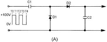
A schematic diagram of a positive step counter is shown in view (A) of figure 4-45. For step
counting, the load resistor of the positive-counting circuit is replaced by capacitor C2. This capacitor is
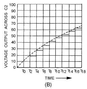
relatively large in comparison to C1. Each time D2 conducts, the charge on C2 increases as shown in
view (B). The steps are not the same height each time. They decrease exponentially with time as the
voltage across C2 approaches the input voltage.
Figure 4-45A.—Basic step counter and waveforms.
Figure 4-45B.—Basic step counter and waveforms.
As long as C2 has no discharge path, the voltage across its terminals increases with each successive
step until it is equal in amplitude to the applied pulse. The voltage across C2 could be applied to a
blocking-oscillator circuit to cause the oscillator to pulse after a certain amount of voltage is applied to it.
The circuit in figure 4-46, (view A) and (view B), may be used as a frequency divider. When used in
this manner, Q1 is used as a single-swing blocking oscillator that is triggered when the voltage across C2
becomes great enough to forward bias Q1. At other times, the transistor is cut off by the bias voltage
developed in the section of R2 that is between the ground and the slide.