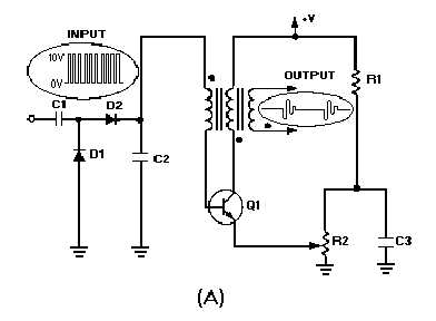
4-52
Figure 4-46A.—Step counter as a frequency divider and waveforms.
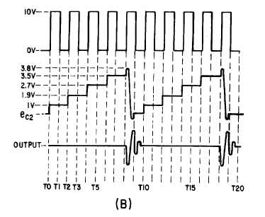
Figure 4-46B.—Step counter as a frequency divider and waveforms.
The action of the counter can best be understood by referring back to figure 4-45. Assume C2 is 10
times larger than C1 and the peak voltage is 10 volts. C1 will assume 9/10 of the positive input voltage at
T0, while C2 will assume only 1/10, or 1 volt in this example. At T1 the input will drop in a negative
direction and D2 will be cut off. The cathode of D1 will become more negative than its anode and
conduct, discharging C1. The charge on C2 will remain at 1 volt because it has no discharge path. At T2
the second pulse will be applied. The 1-volt charge on C2 will oppose the 10 volts of the second pulse,
and the applied voltage for the capacitors to charge will be 9 volts. C2 will again charge 10 percent, or 0.9
volt. This is in addition to the initial charge of volt. At the end of the second pulse, the voltage on C2 will
be 1.9 volts. At T3 the third pulse will be 10 volts, but 1.9 volts will oppose it. Therefore, the applied


