4-27
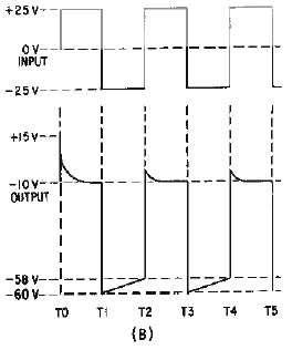
Figure 4-22B.—Negative damper with negative bias.
Let's review the important points of circuit operation. The capacitor is initially charged to
-
10 volts
with no input signal. Applying Kirchhoff's law we find that the +25 volt input signal and the 10-volt
battery are series opposing. This series opposing forward biases D1 and the capacitor charges to
-
35
volts. The output voltage is equal to the sum of the capacitor voltage and the input voltage. Thus, the
output voltage is
-
10 volts and the wave shape is clamped to
-
10 volts. With a
-
25 volt input, the charge
maintained across C1 and the input are series aiding and provide a
-
60 volt output. C1 will discharge just
before the next cycle begins and the input becomes positive. The +25 volt input signal and the
approximately
-
23 volt charge remaining on C1 will forward bias D1 and the output will be clamped to
the battery voltage. C1 will quickly charge to the input signal level. Thus, the output voltage varies
between
-
10 and
-
60 volts and the wave shape is clamped to
-
10 volts.
Negative Clamper With Positive Bias
View (A) of figure 4-23 illustrates the circuit of a negative clamper with positive bias. With no input
signal the capacitor charges to the battery voltage and the output is positive because the negative side of
the battery is grounded. The output is illustrated in the bottom half of view (B). Study the figure carefully
and note the following important points. The peak-to-peak amplitude and shape of the output waveform,
for all practical purposes, are the same as that of the input. The output wave is clamped to +10 volts, the
value of the battery. Since this is a negative clamper (cathode to ground), the top of the output wave
touches the +10 volt reference line.


