4-29
Q6. What is the relative length of the time constant for the diode-capacitor combination in a damper
(long or short)?
Q7. What is the relative length of the discharge time constant with respect to the charge time constant
of a damper (long or short)?
Q8. A positive damper clamps which extremity of the output signal to 0 volts?
Q9. To which polarity does a positive damper with positive bins clamp the most negative extremity of
the output waveform (positive or negative)?
Q10. What type damper (with bias) clamps the most negative extremity of the output waveform to a
negative potential?
Q11. A negative damper damps which extremity of the output waveshape to 0 volts?
Q12. A negative damper with negative bias clamps the most positive extremity of the output wave
shape to what polarity (positive or negative)?
Q13. What type of bias (positive or negative) is added to a negative damper for the most positive
extremity of the wave shape to be clamped above 0 volts?
Q14. What would be the output of a negative clamper with a bias potential of
-
5 volts and an input
voltage swing from +50 to
-
50 volts?
COMMON-BASE TRANSISTOR CLAMPER
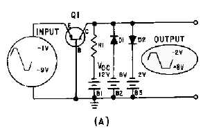
The common-base transistor clamper is similar to the dual diode limiter in figure 4-15, except for the
addition of a transistor. In the previous clampers, we have clamped the output signal to a reference. In the
transistor common-base clamper, we want to clamp the amplitude of the input to no more than nor less
than certain values in the output. Also, we do not want phase inversion in the output. View (A) of figure
4-24 shows such a circuit. The transistor does not amplify the input and the output is not inverted.
However, the two diode circuits serve to clamp the output between
-
2 volts and
-
8 volts, no matter what
the varying input positive and negative extremes.
Figure 4-24A.—Common-base configuration clamper.


