4-28
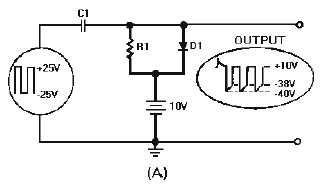
Figure 4-23A.—Negative clamper with positive bias.
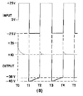
Figure 4-23B.—Negative clamper with positive bias.
Let's go over a summary of the circuit operation. With no input signal the capacitor charges to 10
volts. The +25 volt input signal forward biases D1. With the 10-volt battery and the input in series, the
capacitor charges to
-
15 volts. The capacitor remains charged, for all practical purposes, since its
discharge through R1 (very large) is almost negligible. The output voltage is equal to the algebraic sum of
the capacitor voltage and the input voltage. The +25 volt input signal added to the
-
15 volt capacitor
charge provides a +10 volt output. With a
-
25 volt input at T1, D1 is reverse-biased and the charge across
C 1 adds to the input voltage to provide a
-
40 volt output. From T1 to T2, the capacitor loses only a small
portion of its charge. At T2 the input signal is +25 volts and the input returns to +10 volts. The wave
shape is negatively clamped to +10 volts by the battery.
We can say, then, that positive clamping sets the wave shape above (negative peak on) the reference
level, and negative clamping places the wave shape below (positive peak on) the reference level.


