4-25
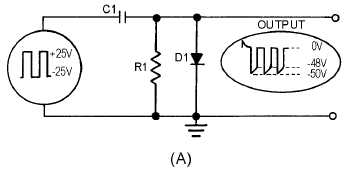
Figure 4-21A.—Negative clamper and waveform.
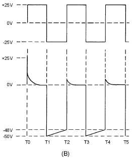
Figure 4-21B.—Negative clamper and waveform.
At T0 the +25 volt input signal applied to the circuit appears across R1 and D1. This makes the
anode of D1 positive with respect to the cathode and it conducts heavily. Diode resistance is very small
causing C1 to charge quickly. As the voltage across C1 increases, the output voltage decreases. The
voltage across C1 reaches 25 volts quickly; during most of T0 to T1, the output voltage is 0.
At T1 the voltage across the capacitor and the input voltage are series aiding and result in
-
50 volts
appearing at the output. At this time the diode is reverse biased and does not conduct. Because of the size
of R and C, the capacitor discharges only 2 volts to approximately 23 volts from T1 to T2. Using
Kirchhoff's voltage law to determine voltage in the circuit, we find that the output voltage decreases from
-
50 to
-
48 volts.
At T2 the +25 volt input signal and the 23 volts across C1 are series opposing. The output voltage is
+2 volts. The anode of D1 is positive with respect to the cathode and D1 will conduct. From T2 to T3, C1
charges quickly from 23 to 25 volts through D1. At the same time, the output voltage falls from +2 to 0
volts.


