3-10
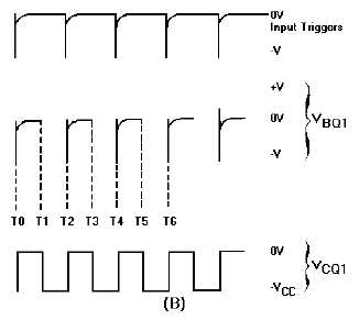
View (B) of figure 3-9 shows the waveforms associated with the circuit. At time T1, Q2 comes out
of cutoff and goes into saturation. Also, Q1 is caused to come out of saturation and is cut off. The base
voltage waveform of Q1 shows a positive potential that is holding Q1 at cutoff. This voltage would
normally hold Q1 at cutoff until a point between T2 and T3. However, at time T2 another trigger is
applied to the base of Q1, causing it to begin conducting. Q1 goes into saturation and Q2 is caused to cut
off. This action repeats each time a trigger (T2, T4, T6) is applied.
Figure 3-9B.—Triggered astable multivibrator and output.
The prt of the input triggers must be shorter than the natural free-running prt of the astable
multivibrator, or the trigger prf must be slightly higher than the free-running prf of the circuit. This is to
make certain the triggers control the prt of the output.
Monostable Multivibrator
The monostable multivibrator (sometimes called a ONE-SHOT MULTIVIBRATOR) is a square- or
rectangular-wave generator with just one stable condition. With no input signal (quiescent condition) one
amplifier conducts and the other is in cutoff. The monostable multivibrator is basically used for pulse
stretching. It is used in computer logic systems and communication navigation equipment.
The operation of the monostable multivibrator is relatively simple. The input is triggered with a
pulse of voltage. The output changes from one voltage level to a different voltage level. The output
remains at this new voltage level for a definite period of time. Then the circuit automatically reverts to its
original condition and remains that way until another trigger pulse is applied to the input. The monostable
multivibrator actually takes this series of input triggers and converts them to uniform square pulses, as
shown in figure 3-10. All of the square output pulses are of the same amplitude and time duration.
Figure 3-10.—Monostable multivibrator block diagram.


