3-8
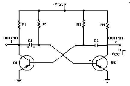
Figure 3-5.—Astable multivibrator.
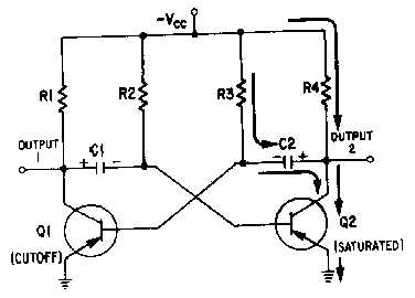
Figure 3-6.—Astable multivibrator. (Q2 saturated).
Notice that figure 3-6 is the mirror image of figure 3-4. In figure 3-6 the left side of capacitor C2
becomes more negative at a rate determined by the time constant R3C2. As the left side of C2 becomes
more negative, the base of Q1 also becomes more negative. When the base of Q1 becomes negative
enough to allow Q1 to conduct, Q1 will again go into saturation. The resulting change in voltage at output
1 will cause Q2 to return to the cutoff state.
Look at the output waveform from transistor Q2, as shown in figure 3-7. The output voltage (from
either output of the multivibrator) alternates from approximately 0 volts to approximately
-
VCC,
remaining in each state for a definite period of time. The time may range from a microsecond to as much
as a second or two. In some applications, the time period of higher voltage (
-
VCC) and the time period of
lower voltage (0 volts) will be equal. Other applications require differing higher- and lower-voltage times.
For example, timing and gating circuits often have different pulse widths as shown in figure 3-8.


