3-11
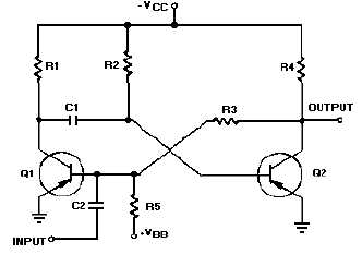
The schematic for a monostable multivibrator is shown in figure 3-11. Like the astable multivibrator,
one transistor conducts and the other cuts off when the circuit is energized.
Figure 3-11.—Monostable multivibrator schematic.
Recall that when the astable multivibrator was first energized, it was impossible to predict which
transistor would initially go to cutoff because of circuit symmetry. The one-shot circuit is not symmetrical
like the astable multivibrator. Positive voltage VBB is applied through R5 to the base of Q1. This positive
voltage causes Q1 to cut off. Transistor Q2 saturates because of the negative voltage applied from
-
VCC
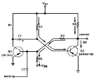
to its base through R2. Therefore, Q1 is cut off and Q2 is saturated before a trigger pulse is applied, as
shown in figure 3-12. The circuit is shown in its stable state.
Figure 3-12.—Monostable multivibrator (stable state).
Let's take a more detailed look at the circuit conditions in this stable state (refer to figure 3-12). As
stated above, Q1 is cut off, so no current flows through R1, and the collector of Q1 is at
-
VCC. Q2 is
saturated and has practically no voltage drop across it, so its collector is essentially at 0 volts. R5 and R3
form a voltage divider from VBB to the ground potential at the collector of Q2. The tie point between these
two resistors will be positive. Thus, the base of Q1 is held positive, ensuring that Q1 remains cutoff. Q2


