3-9
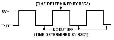
Figure 3-7.—Square wave output from Q2.
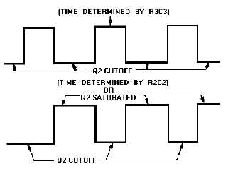
Figure 3-8.—Rectangular waves.
FREQUENCY STABILITY.—Some astable multivibrators must have a high degree of frequency
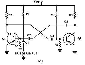
stability. One way to obtain a high degree of frequency stability is to apply triggers. Figure 3-9, view (A),
shows the diagram of a triggered, astable multivibrator. At time T0, a negative input trigger to the base of
Q1 (through C1) causes Q1 to go into saturation, which drives Q2 to cutoff. The circuit will remain in this
condition as long as the base voltage of Q2 is positive. The length of time the base of Q2 will remain
positive is determined by C3, R3, and R6. Observe the parallel paths for C3 to discharge.
Figure 3-9A.—Triggered astable multivibrator and output.


