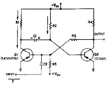
3-12
will remain saturated because the base of Q2 is very slightly negative as a result of the voltage drop
across R2. If the collector of Q1 is near
-
VCC and the base of Q2 is near ground, C1 must be charged to
nearly VCC volts with the polarity shown.
Now that all the components and voltages have been described for the stable state, let us see how the
circuit operates (see figure 3-13). Assume that a negative pulse is applied at the input terminal. C2
couples this voltage change to the base of Q1 and starts Q1 conducting. Q1 quickly saturates, and its
collector voltage immediately rises to ground potential. This sharp voltage increase is coupled through C1
to the base of Q2, causing Q2 to cut off; the collector voltage of Q2 immediately drops to VCC. The
voltage divider formed by R5 and R3 then holds the base of Q1 negative, and Q1 is locked in saturation.
Figure 3-13.—Monostable multivibrator (triggered).
The one-shot multivibrator has now been turned on by applying a pulse at the input. It will turn itself
off after a period of time. To see how it does this, look at figure 3-13 again. Q1 is held in saturation by the
negative voltage applied through R3 to its base, so the circuit cannot be turned off here. Notice that the
base of Q2 is connected to C1. The positive charge on C1 keeps Q2 cutoff. Remember that a positive
voltage change (essentially a pulse) was coupled from the collector of Q1 when it began conducting to the
base of Q2, placing Q2 in cutoff. When the collector of Q1 switches from -VCC volts to 0 volts, the charge
on C1 acts like a battery with its negative terminal on the collector of Q1, and its positive terminal
connected to the base of Q2. This voltage is what cuts off Q2. C1 will now begin to discharge through Q1
to ground, back through
-
VCC, through R2 to the other side of C1. The time required for C1 to discharge
depends on the RC time constant of C1 and R2. Figure 3-14 is a timing diagram that shows the negative
input pulse and the resultant waveforms that you would expect to see for this circuit description.


