2-14
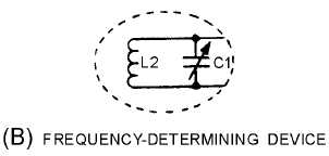
Figure 2-10B.—Basic Armstrong oscillator circuit. FREQUENCY-DETERMINING DEVICE.
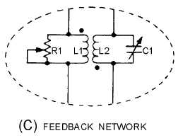
Figure 2-10C.—Basic Armstrong oscillator circuit. FEEDBACK NETWORK.
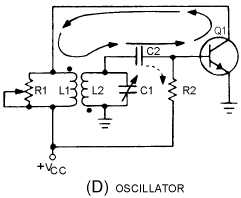
Figure 2-10D.—Basic Armstrong oscillator circuit. OSCILLATOR.
View (B) shows the frequency-determining device composed of inductor L2 and capacitor C1. C1 is
a variable tuning capacitor which is used to adjust the resonant frequency to the desired value.
View (C) is the feedback network which uses L1 (the collector load) as the primary and L2 as the
secondary winding of a coupling transformer to provide a 180-degree phase shift. Variable resistor R1
controls the amount of current through L1. When R1 is adjusted for maximum resistance, most of the
current flows through L1. The transformer now couples a maximum signal which represents a large
feedback amplitude into the tank circuit (L2, C1). If R1 is adjusted for a smaller resistance, less current


