2-16
field in L1, which is coupled into the tank. This feedback action replaces any lost energy in the tank
circuit and drives Q1 toward saturation. After saturation is reached, the transistor is again driven into
cutoff.
The operation of the Armstrong oscillator is basically this: Power applied to the transistor allows
energy to be applied to the tank circuit causing it to oscillate. Once every cycle, the transistor conducts for
a short period of time (class C operation) and returns enough energy to the tank to ensure a constant
amplitude output signal.
Class C operation has high efficiency and low loading characteristics. The longer Q1 is cut off, the
less the loading on the frequency-determining device.
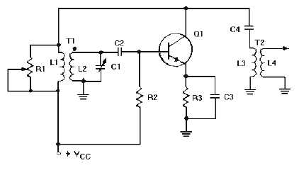
Figure 2-11 shows a tuned-base Armstrong oscillator as you will probably see it. R3 has been added
to improve temperature stability. Bypass capacitor C3 prevents degeneration. C4 is an output coupling
capacitor, and impedance-matching transformer T2 provides a method of coupling the output signal. T2 is
usually a loosely coupled rf transformer which reduces undesired reflected impedance from the load back
to the oscillator.
Figure 2-11.—Tuned-base Armstrong oscillator.
The Armstrong oscillator is an example of how a class C amplifier can produce a sine-wave output
that is not distorted. Although class C operation is nonlinear and many harmonic frequencies are
generated, only one frequency receives enough gain to cause the circuit to oscillate. This is the frequency
of the resonant tank circuit. Thus, high efficiency and an undistorted output signal can be obtained.
The waveforms in figure 2-12 illustrate the relationship between the collector voltage and collector
current. Notice that collector current (IC) flows for only a short time during each cycle. While the tank
circuit is oscillating (figure 2-11), L2 acts as the primary of the transformer and L1 acts as the secondary.
The signal from the tank is, therefore, coupled through T1 to coupling capacitor C4, and the output
voltage across L4 is a sine wave.


