2-13
increase in the oscillating frequency, and an increase in emitter voltage causes a decrease in the
oscillating frequency. This is a result of the change in capacitance between the junctions of the transistor.
However, a common bias source does not completely compensate since the effects on other circuit
parameters of each bias voltage differ.
Just as in any transistor circuit, changes in the transistor operating point and changes in temperature
are encountered in the transistor oscillator. The effects of changes in temperature are to cause collector
current to increase if the transistor is not stabilized. The increase in collector current can be prevented by
reducing the forward bias.
AMPLITUDE STABILITY
The AMPLITUDE STABILITY of a transistor oscillator indicates the amount by which the actual
output amplitude varies from the desired output amplitude.
The same parameters (voltages and currents) that affect frequency stability also affect amplitude
stability. Output amplitude may be kept relatively constant by ensuring that the feedback is large enough
that the collector current is maintained at the proper level. Feedback used in this manner makes the output
voltage directly proportional to the supply voltage. Thus, regulation of the supply voltage ensures good
amplitude stability.
ARMSTRONG OSCILLATOR
The ARMSTRONG OSCILLATOR is used to produce a sine-wave output of constant amplitude and
of fairly constant frequency within the rf range. It is generally used as a local oscillator in receivers, as a
source in signal generators, and as a radio-frequency oscillator in the medium- and high-frequency range.
The identifying characteristics of the Armstrong oscillator are that (1) it uses an LC tuned circuit to
establish the frequency of oscillation, (2) feedback is accomplished by mutual inductive coupling between
the tickler coil and the LC tuned circuit, and (3) it uses a class C amplifier with self-bias. Its frequency is
fairly stable, and the output amplitude is relatively constant.
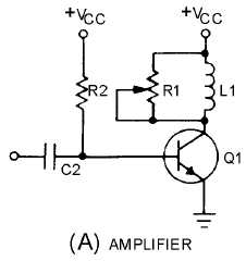
Views (A), (B), and (C) shown in figure 2-10 can be used to build the basic Armstrong oscillator.
View (A) shows a conventional amplifier. R2 provides the forward bias for Q1, C2 is a coupling
capacitor, and L1 and R1 form the collector load impedance. This is a common-emitter configuration
which provides the 180-degree phase shift between the base and collector.
Figure 2-10A.—Basic Armstrong oscillator circuit. AMPLIFIER


