2-17
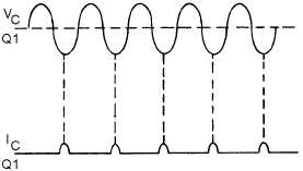
Figure 2-12.—Collector current and voltage waveforms of a class C oscillator.
HARTLEY OSCILLATOR
The HARTLEY OSCILLATOR is an improvement over the Armstrong oscillator. Although its
frequency stability is not the best possible of all the oscillators, the Hartley oscillator can generate a wide
range of frequencies and is very easy to tune. The Hartley will operate class C with self-bias for ordinary
operation. It will operate class A when the output waveform must be of a constant voltage level or of a
linear waveshape. The two versions of this oscillator are the series-fed and the shunt-fed. The main
difference between the Armstrong and the Hartley oscillators lies in the design of the feedback (tickler)
coil. A separate coil is not used. Instead, in the Hartley oscillator, the coil in the tank circuit is a split
inductor. Current flow through one section induces a voltage in the other section to develop a feedback
signal.
Series-Fed Hartley Oscillator
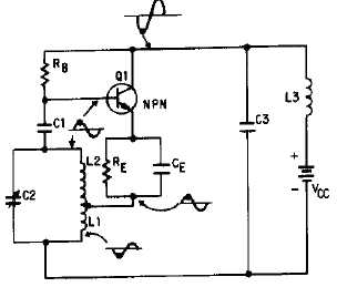
One version of a SERIES-FED HARTLEY OSCILLATOR is shown in figure 2-13. The tank circuit
consists of the tapped coil (L1 and L2) and capacitor C2. The feedback circuit is from the tank circuit to
the base of Q1 through the coupling capacitor C1. Coupling capacitor C1 prevents the low dc resistance
of L2 from placing a short across the emitter-to-base junction and resistor RE. Capacitor C3 bypasses the
sine-wave signal around the battery, and resistor RE is used for temperature stabilization to prevent
thermal runaway. Degeneration is prevented by CE in parallel with RE. The amount of bias is determined
by the values of RB, the emitter-to-base resistance, the small amount of dc resistance of coil L1, and the
resistance of RE.
Figure 2-13.—Series-fed, tuned-base Hartley oscillator.


