2-9
positive feedback is one of the requirements to sustain oscillations in an oscillator. This feedback can be
applied in any of several ways to produce a practical oscillator circuit.
TYPES OF FEEDBACK
Chapter 1 described the resonant or tank circuit and how a sinusoidal signal is generated by the
action of an inductor and a capacitor. The feedback signal is coupled from this circuit by either of two
means. The first method is to take some of the energy from the inductor. This can be done by any one of
the three ways shown in figure 2-7, views (A), (B), and (C). When an oscillator uses a TICKLER COIL,
as shown in view (A), it is referred to as an ARMSTRONG OSCILLATOR. When an oscillator uses a
tapped coil (view (B)) or a split coil (view (C)), it is referred to as a HARTLEY OSCILLATOR. The
second method of coupling the feedback signal is to use two capacitors in the tank circuit and tap the
feedback signal between them. This is shown in view (D). An oscillator using this method is referred to as
a COLPITTS OSCILLATOR. Each of these particular oscillators is named after the person who
originally designed them.
Figure 2-7.—Feedback signals.
CONFIGURATION OF OSCILLATORS
Any of the three basic amplifier configurations (common collector, common base, or common
emitter) described in NEETS, Module 7, Introduction to Solid-State Devices and Power Supplies, Chapter
2, may be used for the oscillator circuit. However, certain considerations in the application of the circuit,
such as the operating frequency and output power required, usually determine which of the three
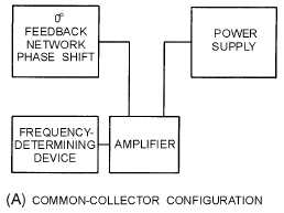
configurations is to be used. The three basic configurations are shown in figure 2-8, views (A), (B), and
(C).
Figure 2-8A.—Basic configurations. COMMON-COLLECTOR CONFIGURATION


