29
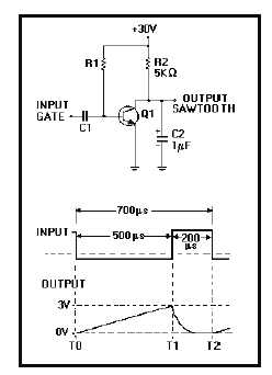
Figure 3G.—Transistor sawtooth generator.
IN ANSWERING QUESTIONS 3-48
THROUGH 3-53, REFER TO FIGURE 3G.
3-48. What component in the circuit develops
the output sawtooth waveform?
1.
R1
2.
R2
3.
C1
4.
C2
3-49. What is the purpose of Q1?
1. Acts as a switch
2. Allows C2 to charge
3. Inverts the negative gate
4. Serves as a common-collector
amplifier
3-50. What is the maximum length of time C2
is allowed to charge?
1. 200 microseconds
2. 500 microseconds
3. 700 microseconds
4. 900 microseconds
3-51. If VCC were increased to 40 volts, which
of the following parameters in the output
sawtooth wave would increase?
1. Fall time
2. Amplitude
3. Sweep time
4. Linearity
3-52. What would be the effect on C2 if the
negative gate length were increased?
1. Charge to VCC
2. Discharge to VCC
3. Charge to a larger percentage of VCC
4. Charge to a smaller percentage of VCC
3-53. What is the prf of the circuit?
1. 1,428 pulses per second
2. 1,450 pulses per second
3. 1,470 pulses per second
4. 1,482 pulses per second
3-54. In a sawtooth generator, a change in
which of the following parameters will
NOT affect the linearity of the output?
1. VCC
2. Resistance
3. Capacitance
4. Gate length
THIS SPACE LEFT BLANK
INTENTIONALLY.


