3-43
TRANSISTOR SAWTOOTH GENERATOR.—The next sawtooth generator uses a conventional
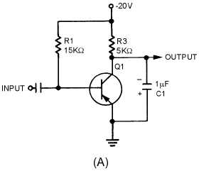
pnp transistor, as shown in figure 3-47, view (A). This generator also uses an RC network, and the
transistor provides the switching action.
Figure 3-47A.—Transistor sawtooth generator (pnp).
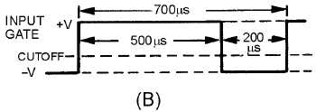
The waveforms for the circuit are shown in views (B) and (C). With no input signals, Q1 is biased
near saturation by R1. The voltage across C1 is very low (-2.5 volts) because load resistor R3 drops most
of the applied voltage. The transistor must be cut off to allow C1 to charge. To cut off Q1, a positive
rectangular wave is used.
Figure 3-47B.—Transistor sawtooth generator (pnp).