4-23
Q19. Does low ripple voltage indicate good or bad filtering?
Q20. Is a full-wave rectifier output easier to filter than that of a half-wave rectifier?
LC Choke-Input Filter
The LC choke-input filter is used primarily in power supplies where voltage regulation is important
and where the output current is relatively high and subject to varying load conditions. This filter is used in
high power applications such as those found in radars and communication transmitters.
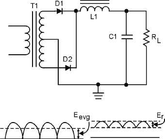
Notice in figure 4-19 that this filter consists of an input inductor (L1), or filter choke, and an output
filter capacitor (C1). Inductor L1 is placed at the input to the filter and is in series with the output of the
rectifier circuit. Since the action of an inductor is to oppose any change in current flow, the inductor tends
to keep a constant current flowing to the load throughout the complete cycle of the applied voltage. As a
result, the output voltage never reaches the peak value of the applied voltage. Instead, the output voltage
approximates the average value of the rectified input to the filter, as shown in the figure. The reactance of
the inductor (XL) reduces the amplitude of ripple voltage without reducing the dc output voltage by an
appreciable amount. (The dc resistance of the inductor is just a few ohms.)
Figure 4-19.—LC choke-input filter.
The shunt capacitor (C1) charges and discharges at the ripple frequency rate, but the amplitude of the
ripple voltage (Er) is relatively small because the inductor (L1) tends to keep a constant current flowing
from the rectifier circuit to the load. In addition, the reactance of the shunt capacitor (XC) presents a low
impedance to the ripple component existing at the output of the filter, and thus shunts the ripple
component around the load. The capacitor attempts to hold the output voltage relatively constant at the
average value of the voltage.
The value of the filter capacitor (C1) must be relatively large to present a low opposition (XC) to the
pulsating current and to store a substantial charge. The rate of the charge for the capacitor is limited by
the low impedance of the ac source (the transformer), by the small resistance of the diode, and by the
counter electromotive force (CEMF) developed by the coil. Therefore, the RC charge time constant is
short compared to its discharge time. (This comparison in RC charge and discharge paths is illustrated in


