4-18
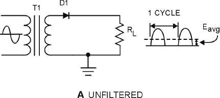
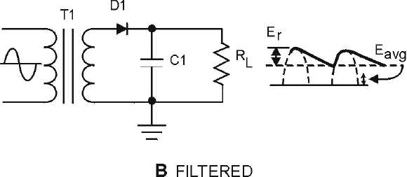
output waveforms in figure 4-16 represent the unfiltered and filtered outputs of the half-wave rectifier
circuit. Current pulses flow through the load resistance (RL) each time a diode conducts. The dashed line
indicates the average value of output voltage. For the half-wave rectifier, Eavg is less than half (or
approximately 0.318) of the peak output voltage. This value is still much less than that of the applied
voltage. With no capacitor connected across the output of the rectifier circuit, the waveform in view A has
a large pulsating component (ripple) compared with the average or dc component. When a capacitor is
connected across the output (view B), the average value of output voltage (Eavg) is increased due to the
filtering action of capacitor C1.
Figure 4-16A.—Half-wave rectifier with and without filtering. UNFILTERED
Figure 4-16B.—Half-wave rectifier with and without filtering. FILTERED
The value of the capacitor is fairly large (several microfarads), thus it presents a relatively low
reactance to the pulsating current and it stores a substantial charge.
The rate of charge for the capacitor is limited only by the resistance of the conducting diode which is
relatively low. Therefore, the RC charge time of the circuit is relatively short. As a result, when the
pulsating voltage is first applied to the circuit, the capacitor charges rapidly and almost reaches the peak
value of the rectified voltage within the first few cycles. The capacitor attempts to charge to the peak
value of the rectified voltage anytime a diode is conducting, and tends to retain its charge when the


