4-20
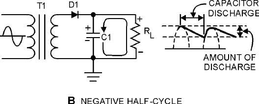
Figure 4-17B.—Capacitor filter circuit (positive and negative half cycles). NEGATIVE HALF-CYCLE
Since practical values of C1 and RL ensure a more or less gradual decrease of the discharge voltage,
a substantial charge remains on the capacitor at the time of the next half cycle of operation. As a result, no
current can flow through the diode until the rising ac input voltage at the anode of the diode exceeds the
voltage on the charge remaining on C1. The charge on C1 is the cathode potential of the diode. When the
potential on the anode exceeds the potential on the cathode (the charge on C1), the diode again conducts,
and C1 begins to charge to approximately the peak value of the applied voltage.
After the capacitor has charged to its peak value, the diode will cut off and the capacitor will start to
discharge. Since the fall of the ac input voltage on the anode is considerably more rapid than the decrease
on the capacitor voltage, the cathode quickly become more positive than the anode, and the diode ceases
to conduct.
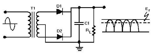
Operation of the simple capacitor filter using a full-wave rectifier is basically the same as that
discussed for the half-wave rectifier. Referring to figure 4-18, you should notice that because one of the
diodes is always conducting on. either alternation, the filter capacitor charges and discharges during each
half cycle. (Note that each diode conducts only for that portion of time when the peak secondary voltage
is greater than the charge across the capacitor.)
Figure 4-18.—Full-wave rectifier (with capacitor filter).
Another thing to keep in mind is that the ripple component (E) of the output voltage is an ac voltage
and the average output voltage (Eavg) is the dc component of the output. Since the filter capacitor offers a
relatively low impedance to ac, the majority of the ac component flows through the filter capacitor. The
ac component is therefore bypassed (shunted) around the load resistance, and the entire dc component (or


