4-13
LC capacitor-input filter (pi-type)
RC capacitor-input filter (pi-type)
The function of each of these filters will be covered in detail in this chapter.
Filtering is accomplished by the use of capacitors, inductors, and/or resistors in various
combinations. Inductors are used as series impedances to oppose the flow of alternating (pulsating dc)
current. Capacitors are used as shunt elements to bypass the alternating components of the signal around
the load (to ground). Resistors are used in place of inductors in low current applications.
Let's briefly review the properties of a capacitor. First, a capacitor opposes any change in voltage.
The opposition to a change in current is called capacitive reactance (XC) and is measured in ohms. The
capacitive reactance is determined by the frequency (f) of the applied voltage and the capacitance (C) of
the capacitor.
From the formula, you can see that if frequency or capacitance is increased, the XC decreases. Since
filter capacitors are placed in parallel with the load, a low XC will provide better filtering than a high XC.
For this to be accomplished, a better shunting effect of the ac around the load is provided, as shown in
figure 4-10.
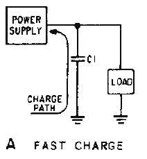
To obtain a steady dc output, the capacitor must charge almost instantaneously to the value of
applied voltage. Once charged, the capacitor must retain the charge as long as possible. The capacitor
must have a short charge time constant (view A). This can be accomplished by keeping the internal
resistance of the power supply as small as possible (fast charge time) and the resistance of the load as
large as possible (for a slow discharge time as illustrated in view B).
Figure 4-10A.—Capacitor filter. FAST CHARGE


