4-9
the upper winding, and back to ground (center tap). When D1 conducts, it acts like a closed switch so that
the positive half cycle is felt across the load (RL).
During the second half cycle (indicated by the dotted lines), the polarity of the applied voltage has
reversed. Now the anode of D2 is positive with respect to ground and the anode of D1 is negative. Now
only D2 can conduct. Current now flows, as shown, from ground (center tap), up through the load resistor
(RL), through diode D2 to point B of T1. In the transformer, current flows from point B up through the
lower windings and back to ground (center tap). Notice that the current flows across the load resistor (RL)
in the same direction for both halves of the input cycle.
View B represents the output waveform from the full-wave rectifier. The waveform consists of two
pulses of current (or voltage) for each cycle of input voltage. The ripple frequency at the output of the
full-wave rectifier is therefore twice the line frequency.
The higher frequency at the output of a full-wave rectifier offers a distinct advantage: Because of the
higher ripple frequency, the output is closely approximate to pure dc. The higher frequency also makes
filtering much easier than it is for the output of the half-wave rectifier.
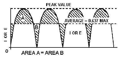
In terms of peak value, the average value of current and voltage at the output of the full-wave
rectifier is twice as great as that at the output of the half-wave rectifier. The relationship between the peak
value and the average value is illustrated in figure 4-7. Since the output waveform is essentially a sine
wave with both alternations at the same polarity, the average current or voltage is 63.7 percent (or 0.637)
of the peak current or voltage.
Figure 4-7.—Peak and average values for a full-wave rectifier.
As an equation:
Where:
Emax = The peak value of the load voltage pulse
Eavg = 0.637
Emax (the average load voltage)
Imax = The peak value of the load current pulse
Iavg = 0.637
Imax (the average load current)
Example: The total voltage across the high-voltage secondary of a transformer used to supply a
full-wave rectifier is 300 volts. Find the average load voltage (ignore the drop across the diode).


