4-5
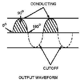
Figure 4-3B.—Simple half-wave rectifier. OUTPUT WAVEFORM
During the negative alternation of input voltage (dotted polarity signs), the anode is driven negative
and the diode cannot conduct. When conditions such as these exist, the diode is in cutoff and remains in
cutoff for 180 degrees, during which time no current flows in the circuit. The circuit current therefore has
the appearance of a series of positive pulses, as illustrated by the shaded areas on the waveform in view
B. Notice that although the current is in the form of pulses, the current always flows in the same direction.
Current that flows in pulses in the same direction is called PULSATING DC. The diode has thus
RECTIFIED the ac input voltage.
Rms, Peak, and Average Values
View A of figure 4-4 is a comparison of the rms, peak, and average values of the types of waveforms
associated with the half-wave rectifier. Ac voltages are normally specified in terms of their rms values.
Thus, when a 115-volt ac power source is mentioned in this chapter, it is specifying the rms value of 115
volts ac. In terms of peak values,
Erms = Epeak
.707
The peak value is always higher than the rms value. In fact,
Epeak = Erms
1.414
therefore, if the rms value is 115 volts ac, then the peak value must be:
Epeak = Erms
1.414
Epeak = 115 volts ac
1.414
Epeak = 162.6 volts


