4-27
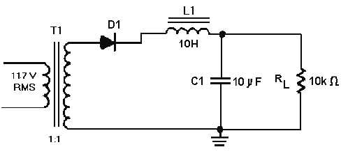
Figure 4-23.—Half-wave rectifier with an LC choke-input filter.
This means that the capacitor (C1) offers 265 ohms of opposition to the ripple current. Note,
however, that the capacitor offers an infinite impedance to direct current. The inductive reactance of L1
is:
The above calculation shows that L1 offers a relatively high opposition (3.8 kilohms) to the ripple in
comparison to the opposition offered by C1 (265 ohms). Thus, more ripple voltage will be dropped across
L1 than across C1. In addition, the impedance of C1 (265 ohms) is relatively low with respect to the
resistance of the load (10 kilohms). Therefore, more ripple current flows through C1 than the load. In
other words, C1 shunts most of the ac component around the load.
Let's go a step further and redraw the filter circuit so that you can see the voltage divider action.
Refer to view A of figure 4-24. Remember, the 165 volts peak 60 hertz provided by the rectifier consists
of both an ac and a dc component. This first discussion will be about the ac component. From the figure,
you see that the capacitor (C1) offers the least opposition (265 ohms) to the ac component. Therefore, the
greater amount of ac will flow through C1. (The heavy line in view B indicates the ac current flow
through the capacitor.) Thus the capacitor bypasses, or shunts, most of the ac around the load.


