4-28
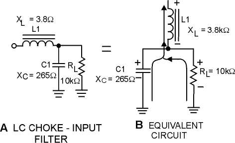
Figure 4-24.—Ac component in an LC choke-input filter.
By combining the XC of C1 and the resistance of RL into an equivalent circuit (view B), you will
have an equivalent impedance of 265 ohms.
As a formula;
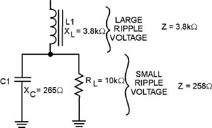
You now have a voltage divider as illustrated in figure 4-25. You should see that because of the
impedance ratios, a large amount of ripple voltage is dropped across L1, and a substantially smaller
amount is dropped across C1 and RL. You can further increase the ripple voltage across L1 by increasing
the inductance (XL = 2
p
fL).
Figure 4-25.—Equivalent circuit of an LC choke-input filter.


