3-31
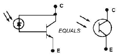
Figure 3-32.—Phototransistor.
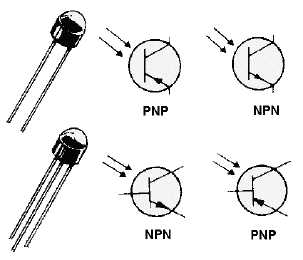
Figure 3-33 illustrates the schematic symbols for the various types of phototransistors.
Phototransistors may be of the two-terminal type, in which the light intensity on the photodiode alone
determines the amount of conduction. They may also be of the three-terminal type, which have an added
base lead that allows an electrical bias to be applied to the base. The bias allows an optimum transistor
conduction level, and thus compensates for ambient (normal room) light intensity.
Figure 3-33.—2-terminal and 3-terminal phototransistors.
An older device that uses light in a way similar to the photodiode is the photoconductive cell, or
PHOTOCELL, shown with its schematic symbol in figure 3-34. Like the photodiode, the photocell is a
light-controlled variable resistor. However, a typical light-to-dark resistance ratio for a photocell is
1:1000. This means that its resistance could range from 1000 ohms in the light to 1000 kilohms in the
dark, or from 2000 ohms in the light to 2000 kilohms in the dark, and so forth. Of course, other ratios are
also available. Photocells are used in various types of control and timing circuits as, for example, the
automatic street light controllers in most cities.