3-35
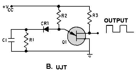
Figure 3-38B.—Comparison of conventional transistors and UJT circuits.
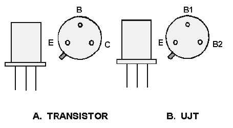
The physical appearance of the UJT is identical to that of the common transistor. As shown in figure
3-39, both have three leads and the same basic shape; the tab on the case indicates the emitter on both
devices. The UJT, however, has a second base instead of a collector.
Figure 3-39.—Transistor and UJT.
As indicated in the block diagram shown in views A and B of figure 3-40, the lead differences are
even more pronounced. Unlike the transistor, the UJT has only one PN junction. The area between base 1
and base 2 acts as a resistor when the UJT is properly biased. A conventional transistor needs a certain
bias level between the emitter, base, and collector for proper conduction. The same principle is true for
the UJT; it needs a certain bias level between the emitter and base 1 and also between base 1 and base 2
for proper conduction.


