3-12
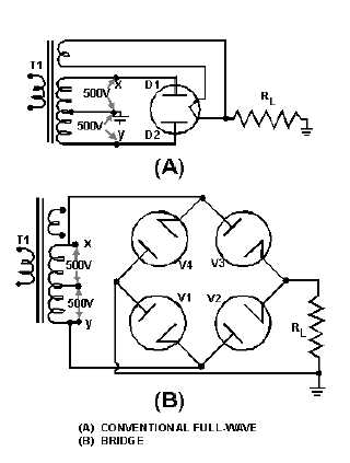
view (A), the peak voltage from the center tap to either X or Y is 500 volts. Since only one diode can
conduct at any instant, the maximum voltage that can be rectified at any instant is 500 volts. Therefore,
the maximum voltage that appears across the load resistor is nearly, but never exceeds, 500 volts (because
of the small voltage drop across the tube). In the bridge rectifier of view (B), the maximum voltage that
can be rectified is the full secondary voltage, 1,000 volts. Therefore, the peak output voltage across the
load resistor is nearly 1,000 volts. Thus, with both circuits using the same transformer, the full-wave
bridge circuit produces a higher output voltage than the conventional full-wave rectifier.
Figure 3-13.—Comparison of conventional full-wave and bridge rectifiers: A. Conventional full-wave circuit
A second advantage of the bridge rectifier is the low ratio of peak inverse voltage to average output
voltage. For this reason bridge rectifiers that use vacuum tubes are widely used in high-voltage power
supply applications.
If directly heated diodes are used in a bridge rectifier, three separate filament transformers are
required. This is due to the different potentials existing at the filaments of the diodes. The filaments of V2
and V3 in figure 3-14 are at the same potential, but the filament of V1 is at a different potential from
either V2 or V4. The three filament transformers must be well insulated from each other, and from
ground, because of the high potentials to which they are subjected. The use of indirectly heated diodes
would solve the filament transformer problem, but the high potential difference between cathode and
heater would be likely to result in arcing.


