3-7
voltage pulses with a value of .318 of the peak value have the same effect on the load as a steady voltage
or current.
The half-wave rectifier uses the transformer during only one-half of the cycle. Therefore, for any
given size transformer, less power is developed than if the transformer were used on both halves of the
cycle. In other words, to obtain large amounts of power, the half-wave transformer must be relatively
large in comparison to what it would have to be if both halves of the cycle were used. This disadvantage
limits the use of the half-wave rectifier to applications that require a very small current drain. The half-
wave rectifier is widely used for commercial ac and dc radio receivers and other applications where
inexpensive voltage supplies will suffice. As you can see from your study on half-wave rectifiers, this
type of circuit placed many limitations on electronic equipment. For this reason another type of rectifier
circuit had to be developed. One of the factors that had to be considered was how to use the full output
from the transformer to obtain the highest average voltage and current. Thus, the FULL-WAVE rectifier
was developed.
Q6. Does a rectifier tube conduct on the positive or negative alternation of the input signal?
Q7. What term is used to describe the period when the diode is not conducting?
Q8. Current that flows in pulses in the same direction is called _____.
Q9. For a diode to act as a rectifier, should it be connected in series or parallel with the load?
Q10. What is the Ripple frequency of a half-wave rectifier if the input frequency is 60 Hz?
Q11. What is the equation for determining average voltage in a half-wave rectifier?
The Conventional Full-Wave Rectifier
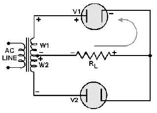
A full-wave rectifier is a device that has two or more diodes arranged so the load current flows in the
same direction during each half cycle of the ac supply.
A schematic diagram of a simple full-wave rectifier is shown in figure 3-8. The transformer supplies
the source voltage for two rectifier tubes (V1 and V2). This power transformer has a CENTER-TAPPED
high-voltage secondary winding that is divided into two equal parts (W1 and W2). W1 provides the
source voltage for V1 and the other winding (W2) provides the source voltage for V2. The connections to
the diodes are arranged so that the diodes conduct on alternate half cycles.
Figure 3-8.—Simple full-wave rectifier (first alternation).


