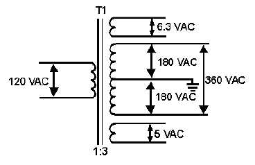
3-3
THE TRANSFORMER
The transformer has several purposes: In addition to coupling the input ac signal to the power supply,
it also isolates the electronic power supply from the external power source and either steps up or steps
down the ac voltage to the desired level. Additionally, most input transformers have separate step-down
windings to supply filament voltages to both power supply tubes and the tubes in the external equipment
(load). Such a transformer is shown in figure 3-3. Because the input transformer is located in the power
supply and is the ultimate source of power for both the load and the power supply, it is called the
POWER TRANSFORMER. Notice that the transformer has the ability to deliver both 6.3 and 5 volts ac
filament voltages to the electron tubes. The High-voltage winding is a 1:3 step-up winding and delivers
360 volts ac to the rectifier. This transformer also has what is called a center tap. This center tap provides
the capability of developing two high-voltage outputs from one transformer.
Figure 3-3.—Typical power transformer.
Q3. What are the purposes of the transformer in a power supply?
Q4. For what are the low voltage windings in a transformer used?
Q5. For what is the center tap on a transformer used?
RECTIFIERS
From previous discussions, you know that rectification is the changing of an ac voltage to a pulsating
dc voltage. Now let's discuss the process of rectification.
Since a diode vacuum tube will pass current in only one direction, it is ideally suited for converting
alternating current to direct current. If an ac voltage is applied to a diode, the diode will conduct ONLY
DURING THE POSITIVE ALTERNATION OF VOLTAGE when the plate of the diode is made
positive with respect to the cathode.
Figure 3-4 shows a diode connected across the 120-volt ac line. During the positive alternation of the
source voltage, the sine wave applied to the tube makes the plate positive with respect to the cathode. At
this time the diode conducts and plate current flows from the negative supply lead, through the
milliammeter, through the tube, and to the positive supply lead. This is indicated by the shaded area of the
output waveform. This current exists during the entire period of time that the plate is positive with respect
to the cathode (for the first 180 degrees of the input sine wave).


