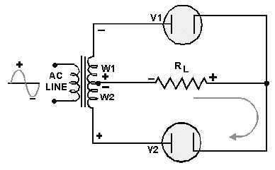
3-8
During one alternation of the secondary voltage, the polarities will be as shown in figure 3-8. The
source for diode V2 is the voltage induced into the lower half of the transformer secondary winding (W2).
At the specific instant of time shown in the figure, the plate voltage on V2 is negative, and V2 cannot
conduct.
Throughout the period of time during which the plate of V2 is negative, the plate of V1 is positive.
This is illustrated by the polarity signs across W1, which indicate the source for V1. Since the plate of V1
is positive, it conducts, causing current to flow through the load resistor in the direction shown by the
arrow.
Figure 3-9 shows the next half cycle of secondary voltage. As you can see, the polarities across W1
and W2 are reversed. During this alternation the plate of V1 is driven negative and V1 cannot conduct.
Figure 3-9.—Simple full-wave recliner (second alternation).
For the period of time that V1 is negative, the plate of V2 is positive, permitting V2 to conduct.
Notice that the plate current of V2 passes through the load resistor in the same direction as did the plate
current of V1. In this circuit arrangement, a pulse of load current flows during each alternation of the
input cycle. Since both alternations of the input voltage cycle are used, the circuit is called a
FULL-WAVE RECTIFIER.
Now that you have a basic understanding of how a full-wave rectifier works, let's cover in detail a
practical full-wave rectifier and its waveforms.
A Practical Full-Wave Rectifier
A practical full-wave rectifier circuit is shown in figure 3-10. It uses two diodes (V1 and V2) and a
center-tapped transformer (T1). When the center tap is grounded, the voltages at the opposite ends of the
secondary windings are 180 degrees out of phase with each other. Thus, when the voltage at point A is
positive with respect to ground, the voltage at point B is negative with respect to ground. Let's examine
the operation of the circuit during one complete cycle.


