3-13
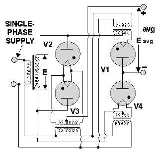
Figure 3-14.—Bridge rectifier with filament transformers.
Q14. What is the main disadvantage of the conventional full-wave rectifier?
Q15. What main advantage does a bridge rectifier have over a conventional full-wave rectifier?
FILTERS
While the output of a rectifier is a pulsating dc, most electronic circuits require a substantially pure
dc for proper operation. This type of output may be provided by placing single or multisection filter
circuits between the output of the rectifier and the load.
There are four basic types of filter circuits:
Simple capacitor filter
LC choke-input filter
LC capacitor-input filter (pi-type)
RC capacitor-input filter (pi-type)
We will cover the function of each of these filters in detail later in this chapter.
Filtering is done by using various combinations of capacitors, inductors, and resistors. Inductors are
used as series impedances to oppose the change in flow of alternating (pulsating dc) current. Capacitors
are used as shunt elements to bypass the alternating components of the signal around the load (to ground).
Resistors are used in place of inductors in low current applications.
Let's briefly review the properties of a capacitor. First, a capacitor opposes any change in voltage.
The opposition to a change in voltage is called capacitive reactance (XC) and is measured in ohms. The
capacitive reactance is determined by the frequency (f) of the applied voltage and capacitance (C) of the
capacitor.


