1-9
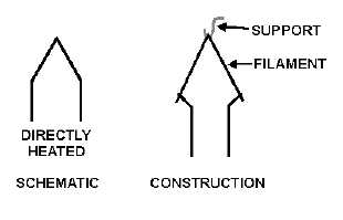
DIRECTLY HEATED.—The filament that has been discussed so far is the directly heated cathode.
Directly heated cathodes are fairly efficient and are capable of emitting large amounts of electrons. Figure
1-6 shows this type and its schematic symbol.
Figure 1-6.—Cathode schematic representation.
An added advantage of this type of filament is the rapidity with which it reaches electron-emitting
temperature. Because this is almost instantaneous, many pieces of electronic equipment that must be
turned on at infrequent intervals and be instantly usable have directly heated cathode tubes.
There are disadvantages. Because of its construction, parts of the filament are closer to the plate than
other parts. This results in unequal emission and a loss of efficiency. Another disadvantage occurs when
dc is used to heat a filament. The filament represents a resistance. When current flows through this
resistance, a voltage drop occurs. The result is that one side of the resistance, or filament, is more negative
than the other side. The negative side of the filament will emit more electrons than the positive side;
which, again, is less efficient than if the filament has equal emission across its entire surface.
When ac is the source of filament power, it causes a small increase and decrease of temperature as it
rises and falls. This causes a small increase and decrease of emitted electrons. This effect is not too
important in many diode circuits, but it is undesirable in other tube circuits.
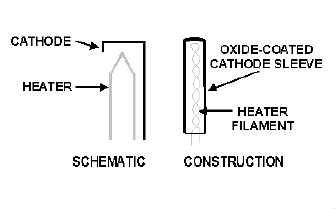
INDIRECTLY HEATED.—Figure 1-7 shows this type of cathode and its schematic symbol.
Indirectly heated cathodes are always composed of oxide-coated material. The cathode is a cylinder, a
kind of sleeve, that encloses the twisted wire filament. The only function of the filament is to heat the
cathode. The filament is often called a heater when used in this manner.
Figure 1-7.—Indirectly heated cathode schematic.


